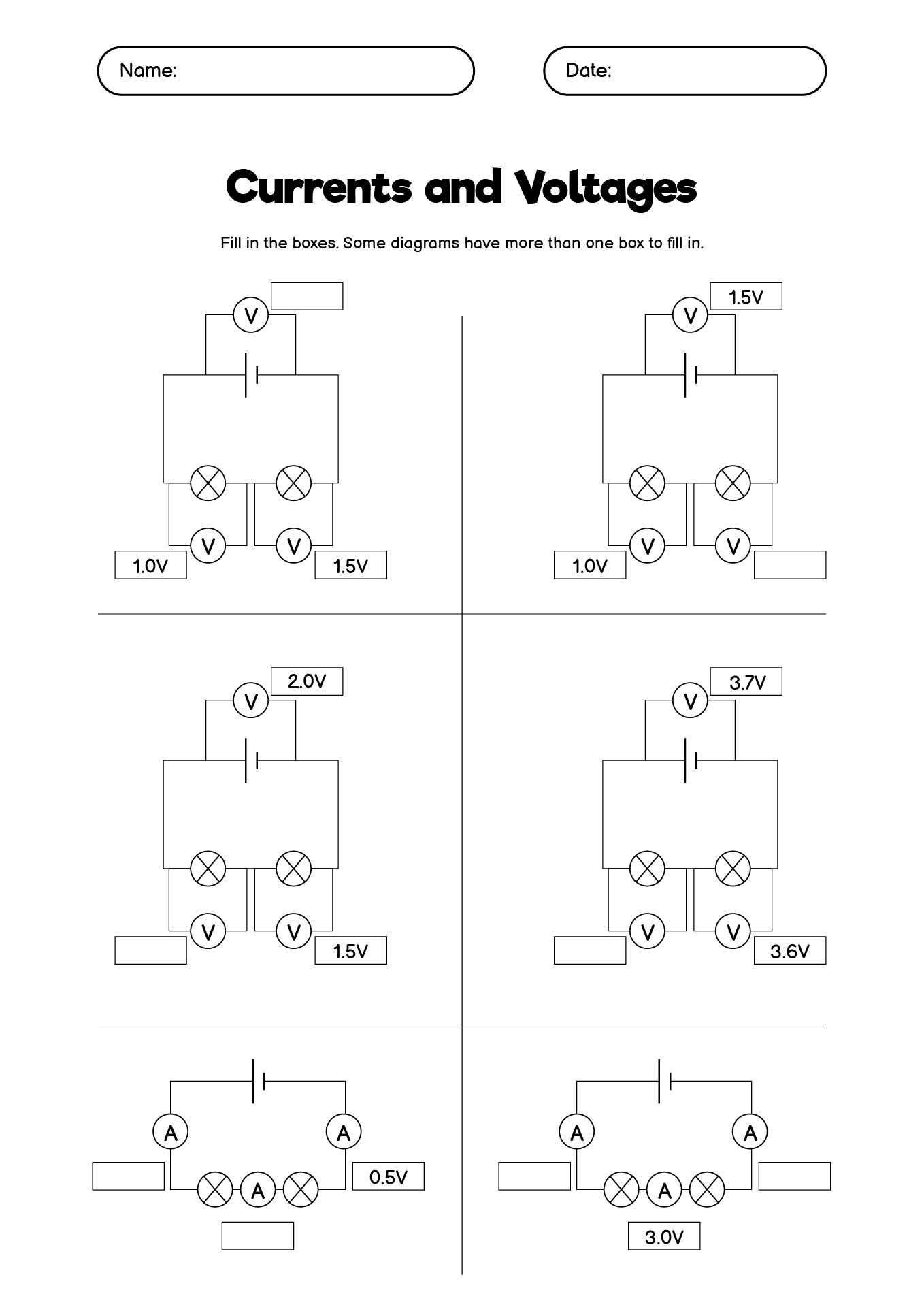
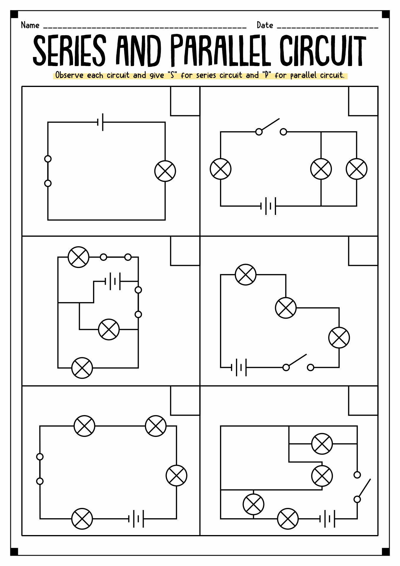
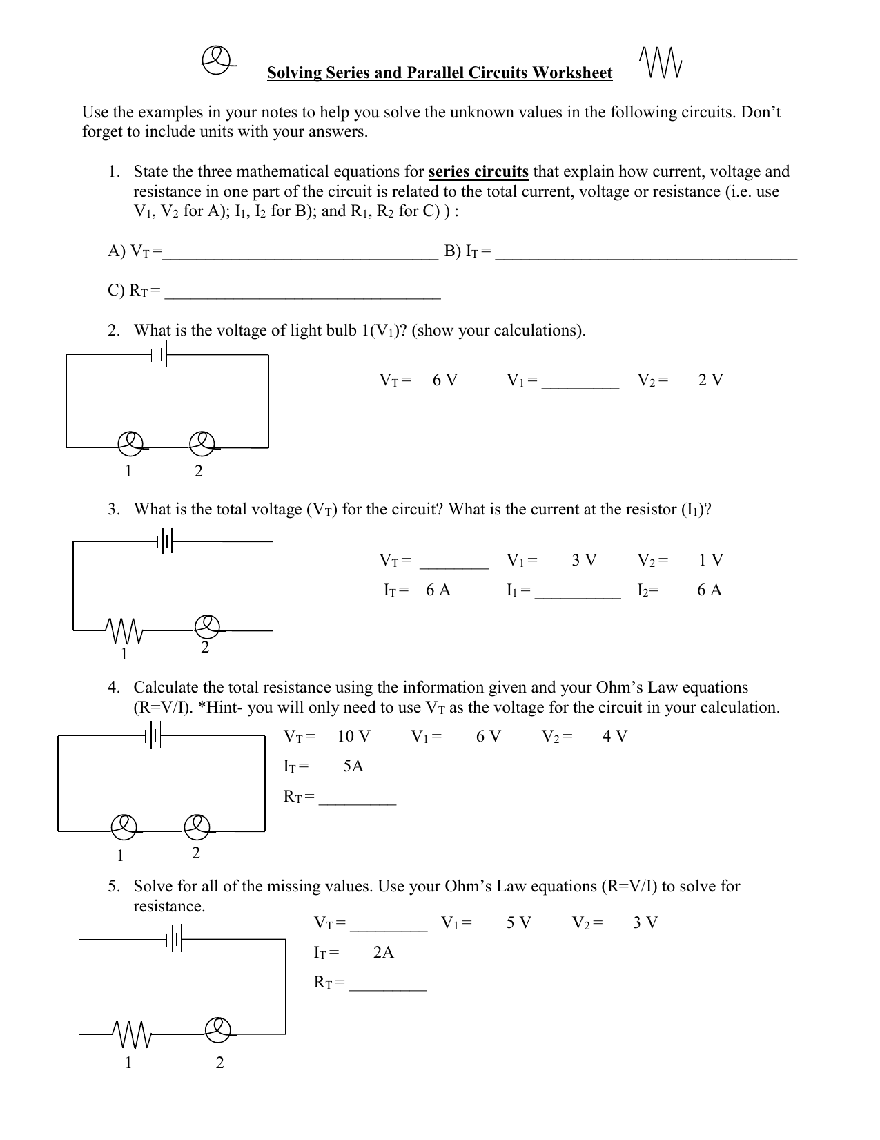
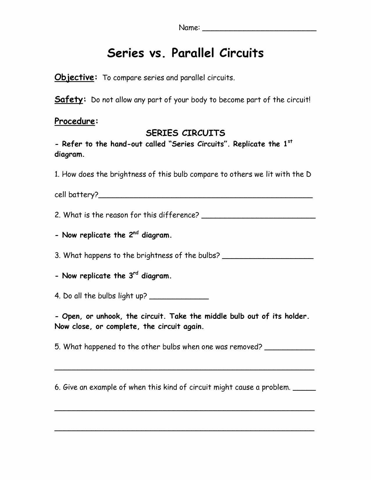
Series And Parallel Worksheet offers a structured way to reinforce foundational concepts of electrical circuits by guiding students through practical problem sets that cover both series and parallel configurations.
Understanding Series Circuits
Basic Principles
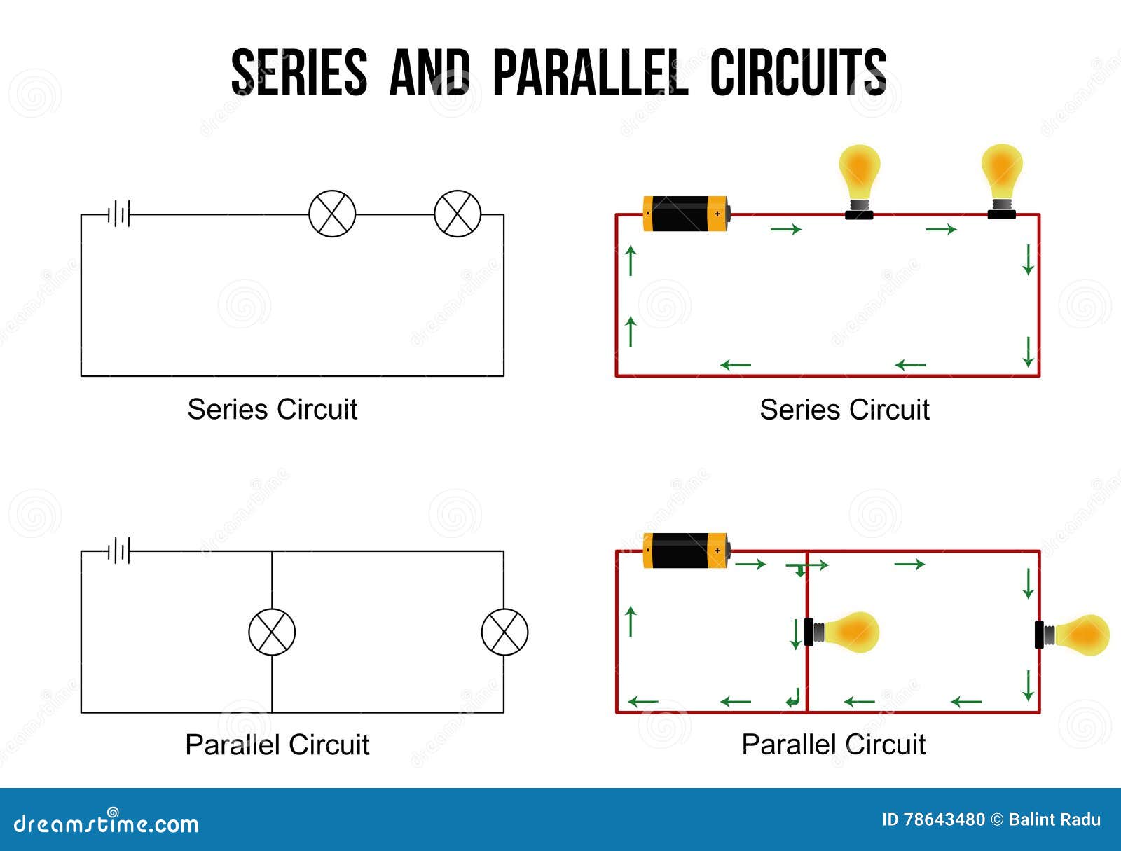
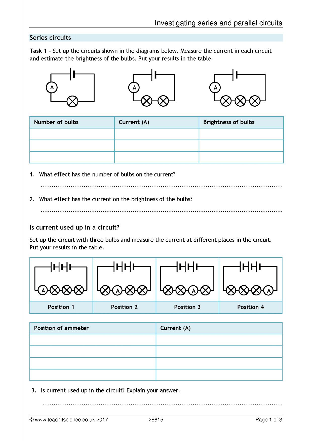
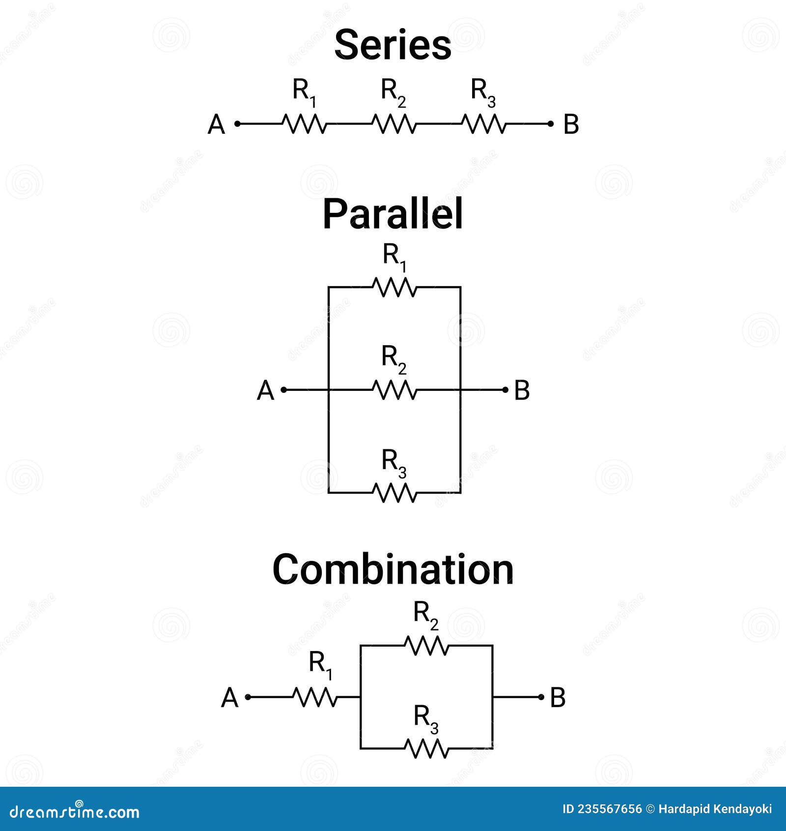
In a series circuit, components are connected end‑to‑end so that the same current flows through each element. The total resistance is the sum of individual resistances, and voltage divides across components proportionally to their resistance values.
Calculating Voltage Drops
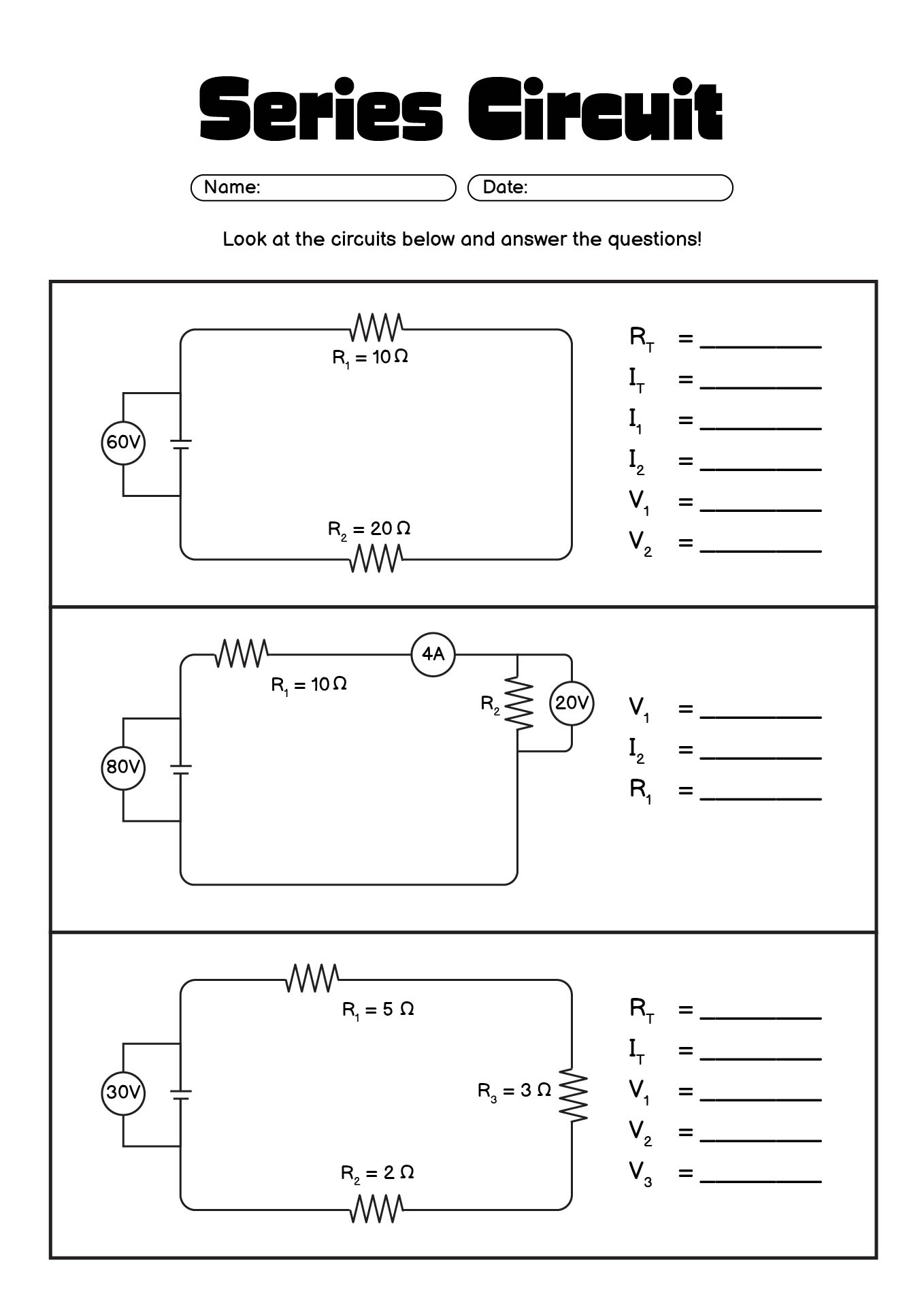
When solving worksheet problems, students should start by calculating the total resistance Rtotal = R1 + R2 + … + Rn. Once the total resistance is known, the total current I can be found using Ohm’s Law, I = Vtotal / Rtotal. Finally, the voltage drop across each resistor is Vi = I × Ri.
Illustrative Example
Consider a simple series circuit with a 9 V battery and three resistors: 2 Ω, 3 Ω, and 4 Ω. The total resistance is 9 Ω. The current flowing through the circuit is 1 A. Voltage drops are: 2 V across the 2 Ω resistor, 3 V across the 3 Ω resistor, and 4 V across the 4 Ω resistor.
Worksheet Tips
Encourage students to:
- Label each resistor clearly.
- Use a consistent method for calculating total resistance.
- Check that the sum of individual voltage drops equals the supply voltage.
Mastering Parallel Circuits
Key Concepts
In a parallel circuit, components share the same two nodes, so the voltage across each element is identical. The total current splits among the branches, and the reciprocal of total resistance is the sum of reciprocals of each branch resistance.
Finding Equivalent Resistance
The worksheet formula is 1 / Rtotal = 1 / R1 + 1 / R2 + … + 1 / Rn. After computing Rtotal, the total current is I = Vtotal / Rtotal, and branch currents follow from Ohm’s Law: Ii = Vtotal / Ri.
Practical Example
A 12 V supply powers two resistors in parallel: 4 Ω and 6 Ω. Equivalent resistance is 2.4 Ω. Total current is 5 A. The current through the 4 Ω resistor is 3 A, and through the 6 Ω resistor is 2 A.
Worksheet Strategies
Students should:
- Sketch the circuit diagram before calculations.
- Compute equivalent resistance first.
- Verify that the sum of branch currents equals the total current.
Combining Series and Parallel
Complex Configurations
Real‑world worksheets often feature mixed networks, where series and parallel elements coexist. The strategy is to reduce the circuit stepwise, starting with the simplest sub‑networks.
Reduction Technique
Identify the smallest series or parallel group, calculate its equivalent value, replace it in the circuit, and repeat until the entire network is collapsed into a single resistance. Then apply Ohm’s Law to find currents and voltages.
Example Scenario
Consider a circuit with a 5 V source, a 2 Ω resistor in series with a parallel pair of 3 Ω and 6 Ω resistors. First, reduce the parallel pair: equivalent resistance is 1.8 Ω. Add the series resistor: total resistance is 3.8 Ω. Current from the source is 1.32 A. Branch currents: 0.88 A through 3 Ω and 0.44 A through 6 Ω.
Practical Worksheet Strategies
Step‑by‑Step Methodology
1. Diagram – Draw a clear, labeled diagram of the circuit.
2. Identify Sub‑networks – Spot series or parallel groups.
3. Reduce – Calculate equivalent resistances and replace.
4. Apply Ohm’s Law – Compute total current.
5. Back‑Solve – Determine currents or voltages in individual branches.
Common Worksheet Challenges
- Mislabeling nodes.
- Forgetting to divide voltage in series correctly.
- Overlooking the reciprocal rule in parallel reduction.
- Incorrectly applying Ohm’s Law signs.
Corrective Practices
Encourage double‑checking each step, verifying units, and ensuring that the sum of individual values matches the overall circuit parameters.
Real‑World Applications
Home Electrical Systems
Understanding series and parallel is essential for designing safe lighting circuits. Series wiring can cause a single bulb failure to shut off the entire string, while parallel wiring ensures each light operates independently.
Electronic Device Design
Battery packs often use series connections to increase voltage, while parallel connections increase current capacity. Balancing these configurations is critical for smartphone battery health.
Automotive Wiring
Automobiles employ parallel networks for critical systems—such as braking and lighting—ensuring that failure in one component does not disrupt the whole system.
Common Pitfalls and How to Avoid Them
Confusing Current and Voltage
Students may incorrectly assume voltage divides like current. Emphasize that voltage drops in series and stays constant in parallel.
Sign Errors in Ohm’s Law
When dealing with power supplies, remember that voltage and current are positive in the direction of conventional flow.
Neglecting Unit Consistency
Always keep units in SI: volts (V), amperes (A), ohms (Ω). Mixing units leads to incorrect answers.
Tips for Educators
Interactive Worksheets
Incorporate drag‑and‑drop circuit builders that let students rearrange components and instantly see the impact on total resistance and current.
Progressive Difficulty
Start with simple series problems, then move to parallel, and finally mixed circuits. This scaffolding helps build confidence.
Real‑Life Contextualization
Link worksheet problems to everyday gadgets—like comparing the resistance of a toaster coil to a LED—so students see relevance.
Formative Assessments
Use quick quizzes after each major section to gauge understanding and address misconceptions immediately.
Conclusion
Mastering the Series And Parallel Worksheet equips students with a robust toolkit for analyzing electrical networks. By systematically diagramming circuits, reducing complex configurations, and applying Ohm’s Law with precision, learners can confidently tackle both textbook problems and real‑world electrical challenges. Continuous practice, coupled with thoughtful feedback, ensures that these concepts become intuitive, paving the way for deeper exploration into electronics and power systems.







Related posts of "Series And Parallel Worksheet"
